Our NEW Optical Transfer Raman technology takes to the next level.
With easy optimization for multiple laser excitation wavelengths, ultra-fine filter adjustments from the outside, and a design that's easy to handle and transport, it's perfect for synchrotron beamlines.
BETSA®
Optical
Transfert
Raman
[BROT] V02
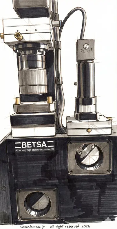
The development of the second version of the BETSA® Raman Optical Transfer (BROT) involved a multidisciplinary approach to optimize optics, electronics, and mechanics, ensuring a high-performance and reliable system.
The design process addressed various constraints and material requirements to guarantee measurement accuracy and performance. See detailed list of key elements and constraints considered for optimizing version V02.
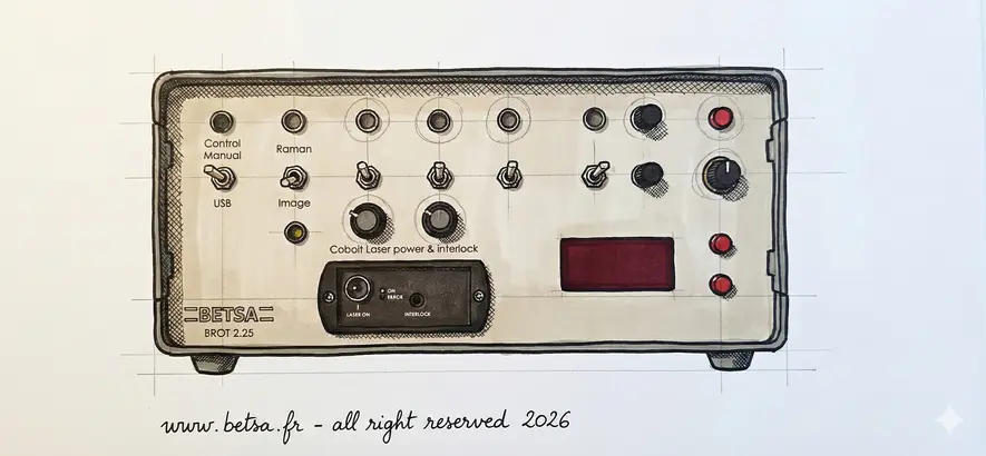
1. Laser Source
- - Type of laser: "Adaptable" diode laser or solid-state laser, fibered or not, with a selectable wavelength of 532 nm, 664 nm, or 945 nm.
- - Laser power: Must be sufficient to excite molecular vibrations without damaging the sample. Typically between 10 mW and 500 mW.
- - Stability and spectral purity: Good wavelength stability and a narrow linewidth are crucial.
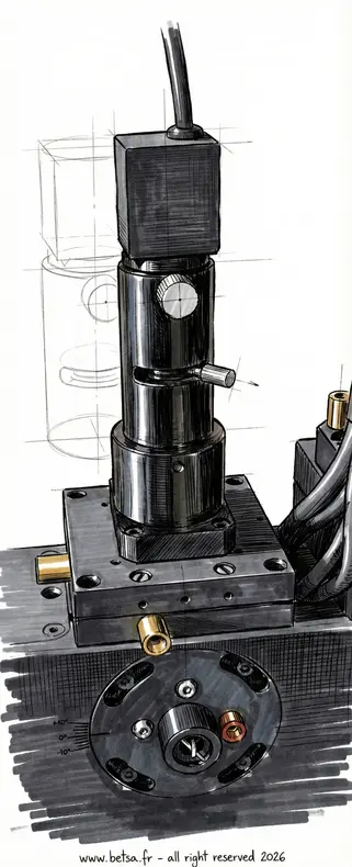
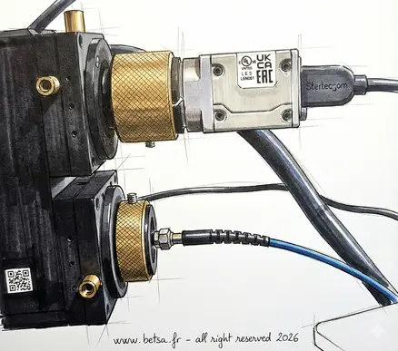
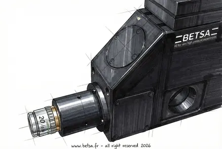
2. Focusing Optics
- Objective: Use high-quality microscopic objectives (10x, 20x) to focus the laser beam on the sample in most DACs and environments.
- Collimators: To maintain a well-aligned and focused beam.
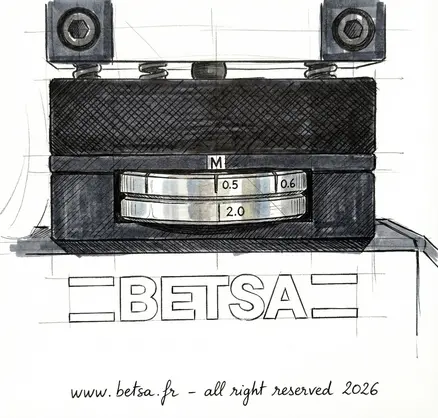
- Notch or edge filters: To block the laser light and allow the passage of the scattered Raman light.
3. Detection
This part is not covered by BETSA®; we only provide the BROT, which will adapt to the client's choice of spectrometer and detector.
- Spectrometer: With sufficient resolution to distinguish Raman bands. Should include an adjustable entrance slit and a high-quality diffraction grating.
- Detector: Cooled CCD to reduce thermal noise and increase sensitivity. EMCCD detectors can be used for applications requiring high sensitivity.
5. Sampling
- Sample holders: Stable and adaptable for different types of samples (solids, liquids, gases).
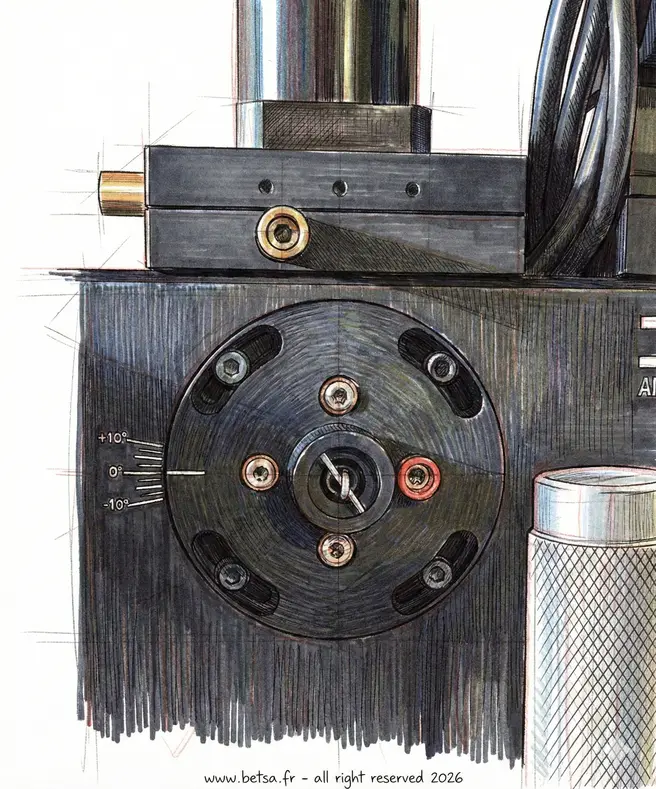
- Microscope: To align and observe the sample, often integrated with the Raman optical head for increased precision. At least 4 XY stages (precision <5µm) for aligning the camera, optical fiber output, light input for internal illumination, and the incoming laser beam coupled with a tilt mechanism.
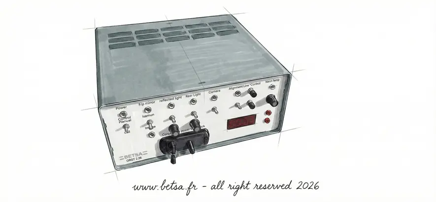
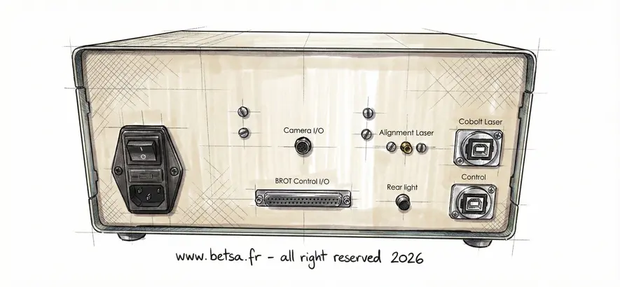
6. Software and Electronics
- Control: Software for laser control, interfacing, and operation.
- Data acquisition: Manufacturer's software for the spectrometer for data collection and spectral analysis.
- Synchronization electronics: To coordinate the operation of the laser, spectrometer, and detector.
7. Environment and Safety
- Cooling: Cooling systems for sensitive electronic components.
- Safety enclosure: To protect the user from laser radiation.
- Vibration isolation: To reduce mechanical noise.
8. Calibration
- Reference standards: Materials with well-known Raman spectra to validate the device's performance.
9.Technical Constraints
- Precise alignment: Necessity for precise optical alignment to maximize Raman signal collection and minimize losses.
- Noise minimization: Importance of minimizing optical and electrical noise sources.
- Temporal stability: The system must be stable over time for repeatable and accurate measurements.